Petrol Tank and Pump
Fuel tank breather pipe
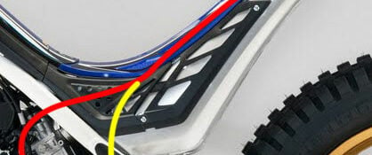
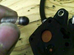
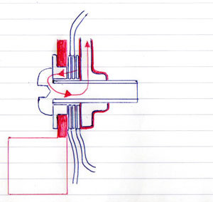
The breather pipe for the petrol tank comes from the factory sticking out of the bottom of the bike (as shown with the yellow line) where it can easily get blocked with mud, water and even snow. If the pipe gets blocked it causes a vacuum in the tank and your bike will run very lean or possibly not at all.
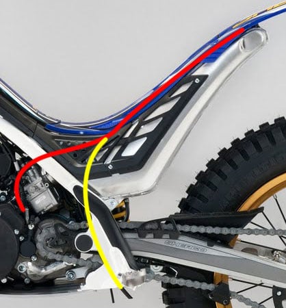
Reroute the breather pipe so it runs over the top of the carburettor and ends down by the clutch slave cylinder keeping it out of the way of most of the muck (as shown by the Red line), the other option is to cut the pipe down so it ends around the top of the rear shock area. Make sure the pipe runs downhill all the way so fuel cannot collect in the pipe and block it. It is also worth making sure the pipe is free from kinks, the clips that hold the pipe in place are not nipping the pipe to tight and that the one way valve is clean, I personally remove this valve from my bikes as I rarely end up upside down and they can sometimes get stuck.
Petrol Tank
The fuel tanks can get a little dirty inside, this muck can cause a restriction to the flow of petrol or even worse get sucked up into the fuel pump all leading to your bike struggling to get enough fuel. Remove your tank every so often and swill out any muck, empty the petrol out into a clear jug so you can see if there is any dirt in there, keep pouring the petrol back in sloshing it about and drain until no more bits come out, drain from the bottom drain hole and the filler cap as there is a divider plate about half way down the tank.
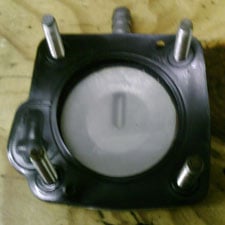
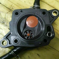
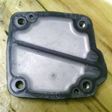
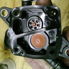
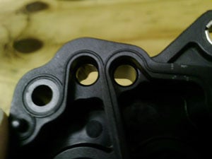
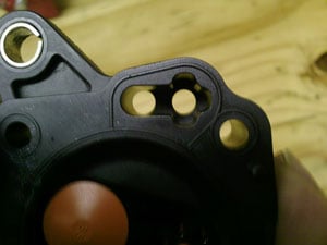
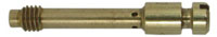
While you’ve got the tank off take the fuel pump off, thoroughly clean the outside of the pump before disassembling it, use a old tooth brush and some petrol, give it a good scrub and blow it dry with a airline, now take the pump to bits by removing the 4 screws, be careful when removing the end caps not to lose the small spring and plastic ball that make up the pressure relief valve, use the air line to blow clean all the internals of the pump and if it’s really bad scrub it with petrol and a brush, ensure the small breather hole on the back end plate is clear and not full of mud. Make sure all the rubber gaskets, diaphragms and umbrella check valves are in good condition, if you find any damage or signs of wear replace, Dellorto Pulse Pump Rebuild Kit.
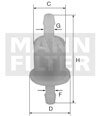
There should be a fuel filter placed between the petrol tank and the fuel pump, use a good quality filter and replace or clean it regularly.
We recommend using the excellent Mann Fuel filter as it has a very fine filter mesh of only 50μm, you’ll need to cut about 25mm out of the petrol pipe down next to your chain and put this filter in its place. The 2011 bikes came with a filter but some became misshaped and let dirt through so we advise swapping it for a Mann filter.
Pump impluse pipe
The rubber pipe that joins the fuel pump to the engine intake should be free of kinks and be in good condition. Make sure the pipe is clean and there are no holes in it, when fitting the carburettor it is easy to trap this pipe under the carburettor or between the carburettor and the rear brake reservoir which will stop the pump from working properly, I personally reroute this pipe to the left side of the carburettor and loosely cable tie it to the clutch cable, in my opinion this gives a slightly better path with larger radius’s and less chance of trapping it.
VHST Carburettor 2011 Sherco 290 only
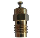
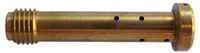
The standard float needle valve that comes with the Sherco trials bikes is a 200, I personally think this is slightly to small as it causes the bike to run lean after full throttle openings, I recommend swapping it for a bigger 250 float needle valve or even a 270 if your doing events like the Scott, the SSDT or trials with road work. When changing the float needle valve it is very important to ensure you reset the float height.
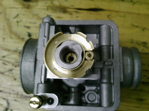
Float height setting
The float height plays a major role in the overall mixture strength of the carburation, as the fuel level rises it makes the distance from the fuel to the air flowing through the carburettor smaller, this makes it easier for the air to suck petrol up through the jets so makes your mixture richer. Through experimentation we found that a float tab height of 18.5mm measured to the bottom edge of the tab from the gasket surface with the carburettor upside down provides a good setting (if using the 270 float valve it is best to make the height to the tab 19.5mm as it tends to flood the bike going downhill at 18.5mm).
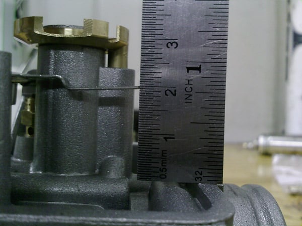
Picture above shows the float height set at 19.5mm from the gasket surface. If your running a 250 float needle valve you may prefer to run this height at 18.5mm.
Fuel Inlet Restrictor
As standard there is a small aluminium restrictor in the fuel inlet on the carburettor which reduces the the inlet down to 2.5mm in diameter, it is important to keep this restrictor in place as it stops the carburettor flooding the engine when doing large endo’s or going down very steep drops, if your running the 270 float valve it may be worth increasing the size of this restrictor to 2.7mm by drilling it out with a 2.7mm drill.

126 as standard, there is also a Anti slosh plate that goes around the outside of the main jet to prevent fuel jumping out from the bottom of the float bowl.
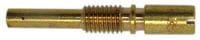
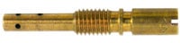
The S33 pilot came as standard but it has very small air bleed holes in the atomiser that can easily get blocked because of this we recommend running the U style pilot jet with the larger holes in the atomiser.
Needle
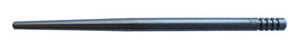
Clip Position
3rd clip down from the top as standard
Slide
50 as standard
Atomiser chimney height
1.6mm as standard
Mudguards
Front
The front mudguard is quite short for our good old muddy English conditions so it is wise to extend the back of the mudguard a bit to help stop mud filling the radiator, it also helps keep you and your bike nice and clean. We have these Front Mudflaps made that stick nicely in place.
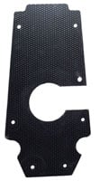
There is a large gap between the bottom of the radiator and the exhaust pipe where mud and water can get thrown off the front wheel on to the electrics, bunging this area up with a large flat sheet of thin plastic helps to stop this and it keep your engine nice and clean. Trick Bits make a nice Sherco engine mud protector which fastens neatly in place with cable ties or we’ve made our own coloured Engine Mud Protector that sticks on to the frame.
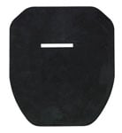
Put a flap at the bottom of the exhaust / petrol tank area so as it stop mud and water spraying on to the rear shock and the linkages, this will keep your shock in better condition and help your linkage bearings to survive for longer. Sherco now make and fit a rubber rear shock mud protector to the 2012 bikes or you can cut a similar guard out of a old inner tube and fit it in the same way.
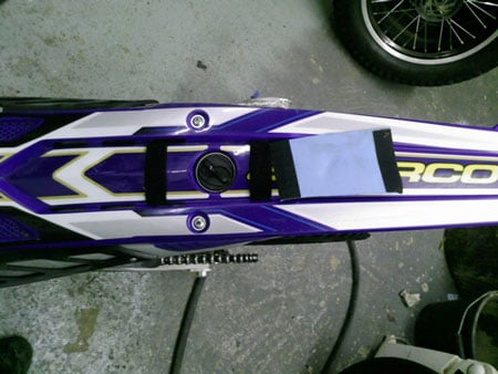
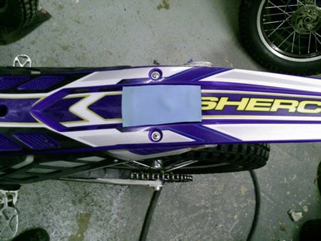
Petrol Filler 2011
Now the new bike comes with the filler on top of the mudguard, in really wet and muddy conditions mud does collect around the filler cap making it difficult to refill the bike without getting muck in the tank, I’ve put a SplatShop Neoprene filler cover on mine that is fastened down using stick-back velcro.
Electrics
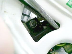
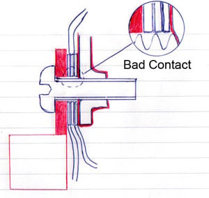
Earth point
The earth tabs connected up under the headstock are semi insulated, on one side there is a powder coated frame and on the other a plastic tab of the regulator so the earth relies on the tabs touching the thread of the bolt. I’ve made a small top hat bush out of aluminium and drilled a bigger hole (8mm) in the plastic tab of the regulator for it to fit through, this gives a better earth point.
Leave a Reply